5.3. Switching voltage regulators
The ideal switch model is suited for all types of circuits. A particularly important class of switched circuits is that of switching voltage regulators. One of the main problems in simulation of such class of circuits is occurrence of inconsistent initial conditions. These conditions occur after switching, when instantaneous change of the capacitor voltage or inductor currents can happen. In such cases, current through capacitor and voltage over inductor have infinite values, but such impulses have infinitely short duration (Dirac impulses). Such problems are usually solved by the application of special algorithms for switched networks [Opal90].
With our model, we have modeled the transition of the switch state, i.e. the switching is not represented just as a replacement of one network topology by another. With our nonlinear model, the switch transition is performed through number of iterations, where, in every iteration, both Kirchhoff laws are satisfied [Mrča99]. Networks with inconsistent initial conditions are solved using standard circuit simulation algorithms. This enables changes in the level of abstraction used in modeling, without change of the simulation environment.
As identified in [Bedr92, Vlac95], the problem of inconsistent initial conditions is not only to conserve the charge and the flux. It is very important to take into account Dirac impulses that can occur in the moment of switching, especially if the network contains internally controlled switches. A Dirac impulse can itself change the states of some switches in the network, thus changing the network topology once more in the same time instant.
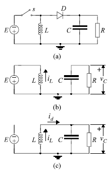
The problem will be depicted by the ideal flyback switching converter, given in Fig. 5.6(a). The switch s represents the transistor that is externally controlled. The diode D is also modeled as ideal switch, but internally controlled. One can model this diode using a control variable p [Bedr92]:

Therefore, the state of the switch D is controlled by the variables in the circuit itself. Let us start the analysis with switch s closed and switch D open. The equivalent circuit is shown in Fig. 5.6(b). Inductor current iL is linearly increasing. When s is externally opened, the inductor current has no closed loop. Therefore, iL must drop instantaneously to zero. Because of that, a Dirac impulse of voltage appears at the inductor. This Dirac impulse changes the switch control variable p to a positive value (eqn. 5.1.), and D becomes closed. Since Dirac impulse has zero duration, D is closed in the same time instant when s is opened. When this happens, the current of the inductor has a closed loop to flow (Fig. 5.6(c)), and there is no discontinuity in the inductor current. Therefore, the

Fig. 5.6: (a) Ideal flyback switching converter. (b) Equivalent circuit for s closed and D open. (c) Equivalent circuits for s open and D closed.
Dirac impulse of the inductor voltage would be erased. There cannot be any impulse of the inductor voltage in simulation results, but the Dirac impulse must appear to switch the diode D, i.e. to change the value of the control variable p. Similar condition happens when s is externally closed. Dirac impulse of current appears through capacitor C, but it opens diode D in the same time instance.
In [Bedr92], special algorithm is developed for simulation of such networks, but with linear elements only. Our switch model enables simulation of such networks using exclusively standard simulation algorithms, and without any restriction in network topology, possible switch states and model linearity. The simulation results for the flyback converter are given in Fig. 5.7. The element values are E=1 V, L=150 mH, C=50 mF, R=10 W. The switching period for the switch s is 70ms, time when s is closed is 30ms, when it is open is 40ms (duty cycle is 3/7). These parameters are not optimized from the point of view of circuit performance.
The results show correct transitions of the internally controlled switch D. The model is nonlinear, since it uses an iterative procedure for transition from one switch state into another. During this procedure, the existence of Dirac impulse is automatically taken into account, although no special algorithms are used for that. Therefore, the Dirac impulse occurs only in the iterative process, but not in the final solution given in Fig. 5.7, where current iL and voltage vC are continuous. However, the Dirac impulse can change the states of other switches in the circuit. The convergence can occur only when all switches in the circuit reach their final state. There is no need to create any special algorithm that would check for the possible occurrence of the Dirac impulses and their influence to the switch states. When the convergence is reached in the whole circuit, all switch transitions are finished and consistent state is obtained, with charge and flux conservation. Details of the switch implementation and analysis of this iterative procedure are given in [Mrča99].
Fig. 5.7: Simulation results for the flyback converter.